Differential Voltage |
A differential voltage source is a source applied to two pins that is realized by applying a time domain waveform to one pin and the waveform's opposite to the other pin. A differential voltage drive applies a voltage at the end of a segment between two specified conductors of that segment. The two conductor ends must be floating. All boundary condition terminations are ignored.
Prior to defining a Differential Voltage Source, the cabling within the segment to be excited should be completed.
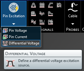
Click Pin Excitation
 within the Excitation section under the MHARNESS tab in the Ribbon. Then select
  Differential Voltage from the drop-down menu.
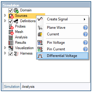
Alternatively, right click Sources in the Simulation Tree and select
 Differential Voltage.
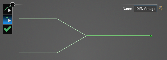
In the top left of the model window, the differential voltage tools will appear.
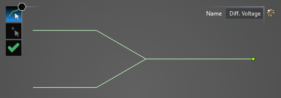
Using the Select Line
 tool, select the line at the end of which the differential voltage will be placed. Hovering above the line will highlight it. The color of the line will not change when selected.
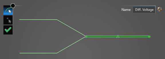
Using the Select Point
 tool, select the termination point at which the differential voltage will be placed. Hovering above the point will highlight both it and the previously-selected line. Termination points not connected to the previously-selected segment will not be selectable.
A new window containing the cable cross section will appear.
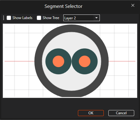
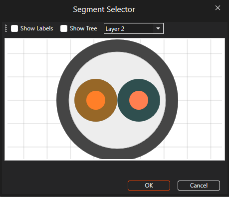
Select the first cable to which the differential voltage should be assigned. It will glow orange once selected. Users may need to use the drop-down menu at the top of the cross section window to change between cable layers. Once selected, click OK.
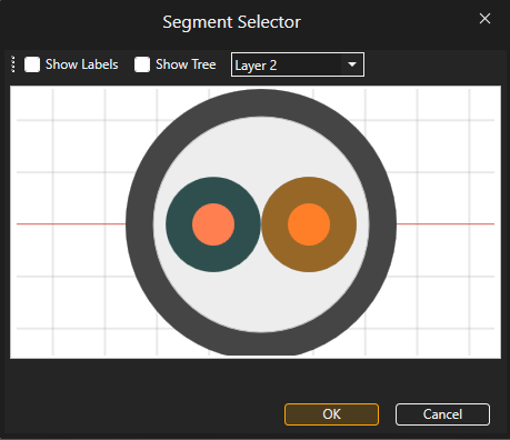
The cross section window will reappear. Select the second cable to which the differential voltage should be assigned. It will glow orange once selected. Users may need to use the drop-down menu at the top of the cross section window to change between cable layers. Once selected, click OK to complete the differential voltage source setup.
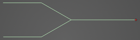
The excited termination point will be recolored red in the model window. Users may need to hide the junction point labels to see the differential voltage source.
The differential voltage source will be added to the Simulation Tree under the Sources node as Differential Voltage. The yellow warning label attached to it indicates that the source needs a signal attached to it.
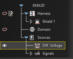
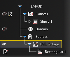
Instructions on adding signals can be found here. Once a signal is attached to the source, the yellow warning label will disappear.
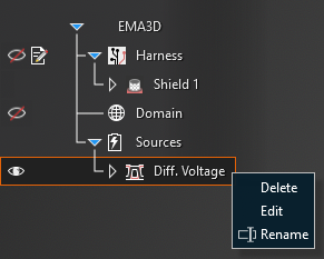
Adjust the definitions of the Differential Voltage Source at any time by right clicking it within the Simulation Tree and selecting Edit from the pop-up menu.
EMA3D - © 2026 EMA, Inc. Unauthorized use, distribution, or duplication is prohibited.